
Demonstration and measurements on superheated steam produced with a self made linear parabolic concentrator using a mirror and an evacuated tube solar collector. Easily tracked concentration of about 1:15.
Steam from the sun on a small DIY home made scale could be used to clean drinking water or to make electricity. I don't think that I have seen it done quite this way.
Before now, my solar concentrator efforts have related to heating a home swimming pool. Making steam was something that happened by accident, usually when we forgot to turn on the circulation pump. Making steam was generally not a good idea around a swimming pool. Besides, that system was designed for high volume, low temperature rise and it does that job well. Making steam on purpose requires some changes.
Yesterday I made steam with the sun intentionally on purpose. My test is crude but it shows what is possible with determination, a few tools and a hardware store.
I set up this test specifically to make steam and to measure the amount produced using the Gen2.0 design DIY solar concentrator. This is only a starting point, a first test.
Last year, I had shown with a similar setup that temperatures of over 600°F (>316°C) could be reached in the evacuated tube at the focus of my home made parabolic trough. I was a bit concerned that there might be trouble with the glass when the relatively low temperature of boiling water was initially introduced. Would it crack and implode the evacuated tube?

(click any pic to enlarge)
In a way, this was an unremarkable test. Once I learned how to start the process and to set the operating point of my equipment, the steam production was steady and reliable.
Because it was a bright sunny day, the steam at the outlet was almost invisible. I don't have the obligatory astonishing pic/vid of large plumes of steam to show you, but it was there. Most times, the only way I could see the steam was to place a dry mirror at the outlet. The mirror would be instantly covered with beads of condensed water from the steam that I couldn't see. Steam production was steady and it was extremely HOT. I measured temperature of 472.2°F (245°C)!
I tried again two days later and the steam is NOT VISIBLE. I measured over 500F. If it has not occurred to you that this is DANGEROUS, you should not read any further - seriously - I take no responsibility. Please be careful if you think you are going to try this at home.
Steam that is hotter than the boiling point of water is dry steam or superheated steam. There is no liquid water in the steam. This is good. If you want to have absolutely clean water or you are running a turbine to make electricity, you want dry steam.
Because this is a focused collector, it needs to face the sun. I had attached my home made reflector motor drive and tracking but I didn't use it. During the one hour test duration, I simply nudged the reflector position about every 15 minutes or so. Position and therefore focus did not seem to be very critical but that deserves more attention. This was a pretty rough test.
By the end of one hour I turned about 1-1/2 cups of water (actual was .334 KG) into steam. That works out to a heat input to the water of 208 watt-hours or 750KJ. I don't address efficiency in this test.
Equipment Description
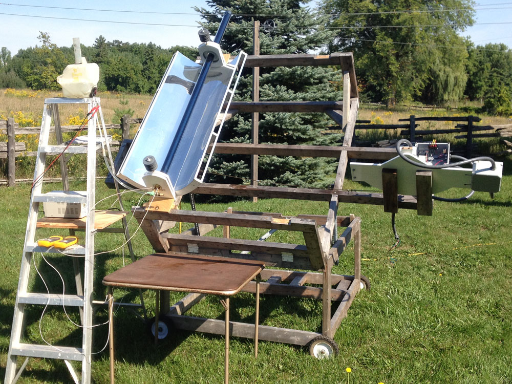
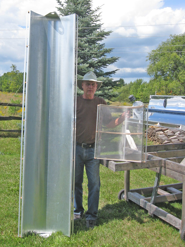
Here is my test setup for the steam test. I am using a four foot (122cm) version of the Gen2.0 parabolic reflector with a six foot (180cm) glass evacuated tube suspended at the 10 cm focal line. The reflector can pivot around the evacuated tube on ball bearing mounts. The test stand has been used in previous tests and is described here.
On top of the ladder is an open top reservoir of water, actually the windshield fluid tank from a 1990 Honda Accord. I had intended to use the small pump on the tank to inject water into the collector but ended up not doing that but simply relying on gravity and the vertical position of the tank to inject water up to a desired level in one arm of the collector (the boiler or "up" leg). Moving the tank to different steps on the ladder accomplished that quite nicely.

I am re-using the rather burnt-out looking collector assembly that I last used for the stagnation test. Although it had over-heated previously since it had no cooling (a definition of stagnation), the solder joints did not fail and it does not leak so I decided to put it to one more good use for this test.
At the yellow arrow, you can see that I have attached a thermocouple (the silver object) to the copper collector by over winding tightly a short length of copper wire. This thermocouple I have called T4 and its purpose is to show the temperature of the steam just before it exits to the air. The fitting to the bottom left will be the outlet, the fitting to the top left will be the inlet. The yellow bung of fiberglass wool is shown wound between and over the collector pipes and the thermocouple wires. When the collector is inserted into the evacuated tube, the bung seals the opening in the tube creating a solar "oven" inside the evacuated tube. The water and the steam will not touch the inside surface of the glass but remain inside the copper tubing. The copper mesh provides some heat coupling between the collector and the inside of the evacuated tube. The mesh may not be necessary.
More details on the construction of this collector.

This schematic view shows my test setup. At the left is the open top water reservoir coupled to the inlet of the collector through a short length of poly tube. The collector forms an inverted U inside the evacuated tube. The outlet of the collector is simply vented to the air as you can see in the first picture above. Also in that pic, you can see the location of the inlet temperature monitor T2 under the green masking tape which holds T2 to the inlet coupling. The purpose of T2 is to show the temperature of the water going into the collector.
The schematic shows the collector as vertical but in fact, the collector, the evacuated tube and the reflector are tilted approximately 45 degrees on the test stand to make them normal to the direction of the sun at my latitude. I did not attempt to get the orientation EXACTLY right. As I said, this was a rough test. I used the shadow of the reflector counterweight to show that the orientation was more or less correct.
T1, the ambient temperature thermocouple is located in the shade under the small table.
T3, the "boiler" temperature thermocouple is located on the collector "up" leg, attached in the same way as T4, approximately co-incident with the top of the reflector or about at the top of the concentrated beam from the reflector. It was intended to show the temperature of that portion of the collector, in the steam above the boiling water.
In a perfect world, I would have the reflector length match the length of the evacuated tube but I have these fine 180cm evacuated tubes to work with as well as 122cm reflectors so the evacuated tube sticks out of the top of the reflector beam for about 20% of its length. A refinement to make for a future test would be to have the reflector better match the evacuated tube and collector. Evacuated tubes are commonly available in standard sizes as I discussed in "more about evacuated tubes".
I believe that it is desirable for a home DIY project to have a type of "flash boiler" in which the water that enters is almost immediately flashed into steam. This would mean very little stored energy in the boiler (safer operation) and a short thermal time constant, meaning that the system would start to operate quickly as there was not a lot of water in the boiler to heat to the boiling point before steam could start to be produced.
Ideally, water would be injected into the inlet at a constant rate to match the rate at which steam is produced. I had planned to do this by regulating the speed of the reservoir pump by changing the supply voltage. Then I realized that a simpler approach was also possible with some compromise to the "flash boiler" concept and that is the approach described above with setting the reservoir on different steps of the ladder to achieve different fluid levels in the boiler.
Operation
As I said above, I had intended to use the small reservoir pump to feed the collector "boiler" but I was concerned about introducing water into an already hot collector and also about matching the rate of evaporation with the feed rate of the pump. My attempts to feed water in short bursts or at a slow rate simply lead to angry bursts of steam from the outlet and then nothing as the collector cooled down and evaporation essentially stopped until the collector (and the water it contained) heated up again.
The compromise was to try different vertical levels of the reservoir and to not use the pump. Lifting or lowering the reservoir causes the fluid level to correspondingly rise or fall in the collector, like with a fluid manometer. As water boils and evaporates, replacement fresh water will flow in and the level will stay the same as the level in the reservoir.

With the reservoir at the top of the ladder, the water level was too high and the steam that resulted came in bursts with burbles of liquid water, often in violent bursts. You can see the water on the table in this enlargement. The puddle was actually quite a bit larger earlier in the test. I interpret this as liquid water being kicked over the top of the U and then exiting the outlet with the steam. Liquid water is not good in the output of a steam generator. Operation was not steady.
With the reservoir a couple rungs down the ladder, the steam flow was steady but seemed to be coming at a lesser rate. So by trying a few variations, I found the second step from the top of the ladder, or a water level in the collector about 1/2 way up the boiler section of the "up" leg gave steady steam with no burbling, in other words, no water at all coming out at the outlet, just steam.
To start, I set the reflector out of focus. The evacuated tube was fully exposed to the sun but not concentrated sunlight. This allowed the interior of the tube to heat without solar concentration as it would normally do in the water heating application where these tubes are typically used, without a reflector. I left it this way for about one hour to preheat.

It is interesting that in this condition, without the reflector, no detectable steam was produced. In other words, the collector did not get hot enough to boil. In my previous stagnation test, the collector was empty and the the collector temperature soared. By keeping the boiler about 1/2 full of water it is heated close to the boiling point but did not reach that (without concentration). T3 - the temperature at the top of the boiler, was about 250°F (121°C) and T4 - the outlet temperature was similar at about 235°F (113°C). Hot enough to boil water if there was any water at those levels but there isn't. I am speculating that there is sufficient convective loss through the water out the inlet fitting to suppress further rise in temperature or phase change. The temperatures shown in the pic are at this stage.
The Test
Spinning the reflector into focus changed everything. Within only a few minutes, I saw wisps of steam and within maybe 10 minutes, I could see a steady jet of steam at the outlet of the collector by using the hand mirror.
At this point, with steam produced at a uniform rate and no liquid water exiting the collector, I weighed the reservoir using a digital scale. Then I left everything alone except for checking focus periodically to match the sun's travel and checking the temperatures.
At the end of an hour, I had 0.334KG less water in the reservoir by weight than at the start of the test. There were no water leaks. My conclusion is that 0.334 KG of water had been turned into steam and had left the system through the outlet.

The temperatures during the steam test (while using the concentrator) were quite interesting. The ambient temperature T1 has risen just a bit to 103.7°F (40°C). It was a hot day (no clouds, no wind) and the test was just before solar noon. T2, the inlet temperature at 116.8°F (47°C) is a bit higher than ambient since the liquid water at the inlet is being heated from the boiler above it. T3, at the top of the boiler is about the same as without the reflector at 224.6°F (107°C). The outlet temperature is the really surprising one. Yes, you see that correctly in spite of the bad pic, 472.2°F (245°C)!
My interpretation of the outlet temperature is that the "down" leg of the collector heats substantially in the focused beam raising the possibility that the steam is being superheated before it exits the collector while also vaporizing any errant liquid water that happens to burble over the top of the U.
Conclusions
Not a bad first attempt I think to mock up a potentially viable and practical solar steam source using a DIY approach while keeping things relatively safe.
As I said, this was a crude effort. Regardless, I was pleasantly surprised by the number of interesting things the test showed me and I have tried to describe them here. There are lots of rough edges and things that could be improved and re-tested.
This is a work in progress. I am grateful for any comments or suggestions you may have.
Thank you for your interest.
George Plhak
Lion's Head, Ontario, Canada
[to the gen2 intro and reading list]