Friday, October 14, 2011

Index - Comparing concentrator to flat plate solar collector

I have compared the heating performance of two interesting home built DIY (Do It Yourself) solar collectors: a traditional flat plate collector and a concentrating parabolic trough collector. The tests involved mounting both at the same time in a solar test jig which allows precise aiming of the collectors at the sun's track. Both insulated and non-insulated configurations of each collector design were built and tested. Both solar tracked and stationary mountings were used for the flat plate collector. The concentrating collector requires tracking for it to function.

As a part of the tests, a new approach is presented for making an insulated concentrator collector as an extension of the design presented in my plan book How to build a tracking parabolic solar collector.

This is a work in progress and the entries as written in this blog probably aren't in the best order to read about my testing project. The index below ties together the related posts in the recommended reading order.

INDEX
Compare concentrator to flat plate solar collector DIY

Summary/Conclusions
Compare to flat plate collector?
Solar test jig
Data recorder and accuracy
1 Comparing concentrator to flat plate solar collector
Uninsulated, stationary flat plate
2 Comparing concentrator to flat plate solar collector
Uninsulated, both track
Insulating the flat plate collector
An insulated collector for the concentrator
3 Comparing concentrator to flat plate solar collector
Insulated, stationary flat plate
4 Comparing concentrator to flat plate solar collector
Insulated, both track
Stagnation test
Concentrator absorber condition after stagnation test
More about evacuated tubes

If you have a comment or suggestion on the project please leave it here or write me directly. Comments here are moderated for spam.

Thank you for your interest.
George Plhak
george (at) ffwdm (dot) com

[to the gen2 intro and reading list]

Monday, October 10, 2011

5 Comparing concentrator to flat plate solar collector - stagnation

The test today involved measuring the stagnation temperature of both the flat plate and the concentrating solar collectors used up to now in this series of comparative tests. The stagnation temperature is the temperature reached with no fluid flow such as when the pump fails or the owner forgets to turn on the system. It is important for solar collectors to be able to withstand the stagnation temperature without damage. Another interpretation of the stagnation temperature might be the highest temperature that can be reached with fluid speed of near zero.

As this might have been a destructive test, I left it to nearer the end of my tests.

Truthfully, the test today was conceived and executed in a bit of a hurry. I did not plan to do testing today. But when I noticed shortly before solar noon that the polyethylene hoses had melted from the brass fittings on the concentrator that I began to wonder just how hot it was inside the glass evacuated tube? and inside the flat plate box? I had not been running the pumps so this was truly stagnation on a bright, hot clear fall solar day.

I could not use the HOBO date recorder for this test since the probes that I have are spec'd only to 212°F and likely the temperatures would be higher than this. Fortunately, I had at hand my trusty Fluke 52II dual channel thermometer and a couple of high temperature thermocouple probes rated to 1000°F.

I drilled a hole in the plastic horizontal closure strip on the top of the flat plate collector and inserted one of the thermocouple probes so that is was resting on the aluminum absorber plate about 6" from the top of the collector.

For the concentrator, I pulled out the fiberglass bung and the copper tubing loop far enough to unwind the bung down to where the copper tubes passed through and laid in the other thermocouple wire so that the probe was inside about 6" from the top of the evacuated tube and then rewound the bung and reinserted it into the evacuated tube.

The tracker was out of focus for the concentrator for the time of day. So the beginning results might be indicative of the stagnation temperature of an evacuated tube as normally used, without a reflector. Clearly from the starting temperature (378°F) the water inside had long since boiled away.

I was working on something else nearby and periodically took pictures of the Fluke display for both the concentrator (channel 1) and the flat plate (channel 2). I used the time of day recorded by the camera to construct the graph using Microsoft Excel. The time of day is not daylight savings, so to compare to the other tests one hour should be added.

(click to enlarge) As the concentrator came into focus, the temperature increased dramatically to a maximum of 636.1°F! By this time, the sky contained high altitude haze that limited any further increase.

The flat plate collector on the other hand stayed at about 200°F for the entire test, dropping off earlier than the concentrator which caused me to look at the sky and to notice the haziness. Ambient air temperature during the test was between 76-80°F. The air was still, there was no wind at all. Both the concentrator and the flat plate collector were tracking the sun.

Over six hundred degrees inside the concentrator collector! Wow!

I will pull out the copper tubing loop tomorrow to check the soldered connections.

No damage seems apparent to the flat plate. I was worried about the foam polystyrene insulation but it seems not to have melted.

Index - Comparing concentrator to flat plate solar collector

4 Comparing concentrator to flat plate solar collector

In this test, both insulated collectors track the sun. The flat plate on the left and the concentrating parabolic reflector on the right are coupled to the solar tracker and motor drive on the far right. Although flat plate type collectors are not normally used in a tracking configuration, I wanted to see how the collectors compared when used in this way. All other aspects of the solar test jig were unchanged from the previous tests.

Unlike the previous tests, here the flat plate shows a slight advantage over the concentrator. The flat plate begins heating more quickly and cools less quickly. During the period around solar noon, the curves are virtually the same. Overall, the curves are pretty close, suggesting that the characteristics of the two collectors are very similar when used in this configuration.

Early in the test, I had a problem with the temperature sensor for the concentrator. Fortunately, I had a look at the data being logged at about 09:45 and was able to correct the sensor problem just in time as the sun hit both collectors. You can probably get an idea of the concentrator temperature during this period by joining the tops of the readings. After the sun hits, the data is clean.

This is an enlargement of the period around solar noon. The curves are virtually identical, usually within a degree F. As in the previous test, the tracker reaches it's western limit just after 16:00 and the concentrator collectors falls out of the beam about 30 minutes later. The flat plate does not fall in temperature as quickly since it is still picking up some heat until the sun sets.

The maximum for both is pretty hard to pick out. The actual peak for the flat plate of 131.939F occurs at 15:43 which is 51.4 degrees F above ambient. At that time, the concentrator is 131.107F, within one degree F or virtually the same.

Index - Comparing concentrator to flat plate solar collector

Sunday, October 09, 2011

3 Comparing concentrator to flat plate solar collector

In this test, both solar collectors in the solar test jig are insulated. The flat plate collector is fixed in position in the same way as these are normally used. The concentrating parabolic trough collector rotates automatically to face the sun as these are usually used (and the way they must be used for them to operate properly).

Details of the insulation for each collector are given in previous postings, for the flat plate and for the concentrator. More background on the test methodology and the collectors is here.

Temperatures in the two separate reservoirs (red picnic coolers) were logged automatically throughout the day as was the ambient temperature in a shaded location near the solar test jig. Each reservoir holds a small aquarium pump that circulates the fluid through each collector and back to it's reservoir. The flow rates of the fluid (water) were monitored on two flow gauges and balanced to be the same 0.85 LPM. The quantity of water in each system was the same 45 lbs (20.5 kg). The plumbing runs are identical lengths and sizes for the two systems.

The day was a perfect solar day (rare here at this time of year): clear blue sky, no clouds and only a slight breeze 10-20 KPH during part of the day.

Here are the overall results for the day. Both systems start to heat rapidly as the direct sun hits them about 09:45. The concentrator has a slight lead until about 13:45 when they begin to run almost identical temperature profiles until about 15.20 when the flat plate abruptly begins to cool while the concentrator continues to rise in temperature.

The tracker, which in this test is controlling only the concentrator position, reaches the end of it's travel at just after 16:00. The concentrator collector remains in the beam for over a half an hour further and the temperature of the concentrator curcuit continues to rise until about 16:45 when the collector finally leaves the beam and the concentrator temperature begins to fall.

The temperature of both systems falls rapidly until the end of the test at 19:30 at which time the sun is setting.

At the beginning of the day, both collector temperatures rise with the ambient although the concentrator does not rise as quickly as the flat plate. This may indicate that the insulation of the concentrator collector might be slighly better than the insulation of the flat plate if the other factors of each system were truly the same.

The solar test jig is shielded from the rising sun by a row of trees so the exposure as the sun rises is not even, hence the undulating solid line of the concentrator temperature from about 08:50 until full exposure to the sun occurs at about 09:40 and indeed the flat plate temperature from about 09:30 to 09:40.

The pumps, by the way, have been running all night to even out the temperatures at startup.

In this zoom on the period around solar noon, you can see that the two systems seem to track each other from about 14:00 to 15:20. This would seem to indicate that when near normal to the sun at its zenith, the efficiencies of the two solar collectors I am testing are more or less the same under the test conditions.

The peak concentrator temperature of 129.876F occurs at 16:45. This is 50.2 degrees F above ambient. For the flat plate, the peak of 128.998F occurs earlier, at 15:17. This is 49 degrees F above ambient.

Tomorrow, I will test again, with both the flat plate and the concentrator tracking the sun.

Index - Comparing concentrator to flat plate solar collector

Saturday, October 08, 2011

insulated collector for the concentrator

My previous experiments had used a bare mat black painted copper collector tube at the focus of a parabolic trough to capture heat. By introducing an insulator around the collector, it will be possible to reduce heat loss to the air which becomes severe during cold weather or when there is wind. Higher temperatures should also be possible.

Evacuated tube solar collectors (click pictures to enlarge) don't seem to be as common in North America but are in wide use elsewhere. The systems employ glass "thermos bottles" with a selective coating inside to trap the sun's heat. The interior contains a heat pipe. The heat pipe conducts heat to a metal bulb at the end which couples thermally into an insulated manifold through which circulates the heated fluid. Here is an example of one such commercial system with an explanation of how it works

Fortunately due to high production volumes in China and India, the evacuated tubes are relatively inexpensive. I paid about $20 each for mine, a lot less than buying industrial glass tubing.

These type of commercial systems do not incorporate a large area concentrator. The heat captured in each tube is related to the area of the tube that faces the sun and maybe a bit on the back from the snow as a reflector in winter, some say. I felt that the usefulness of the tubes could be increased and less of them would be required if they were used at the focus of a concentrating reflector. The power into each tube could be increased, up to about 15x with my current concentrator. Would this be too much heat?

I had read that the heat pipes used are rated for a maximum of about 125 watts and I anticipated getting much more heat from the concentrator, perhaps 800 watts. Also, there was the difficulty of scaling up the manifold to the higher heat captured. So I had decided to remove the provided heat pipes and substitute a pipe loop into the interior of the evacuated tubes and to run my fluid directly through the evacuated tube.

Here I am beginning to remove the heat pipe from the evacuated tube. This one came out easily by simply pulling on the bulb. Others did not yield so easily as the heat pipe came out by itself and the glass fiber bung had to be picked out and then the aluminum heat coupler had to be pulled out with pliers. Different manufacturers use different designs for their heat pipes and mounting. This is only one example.

All evacuated tubes that I have seen are open at only one end. So it is necessary for the collector pipe to make a sharp bend at the bottom of the evacuated tube. The inside ID of the evacuated tubes that I am using is 43 mm. Here I have tried to create a bend to fit this diameter in 3/8" OD soft copper refrigeration line using a pipe bender. You can see that the tubing has crushed beyond usability. I had to find another way.

Commercial 90 degree elbows are just a bit too long so it was necessary to trim about half of one side of each of these elbows to create a 180 degree bend that would fit down the inside of the evacuated tube.

This is the final soldered result. I used silver solder at the shortened middle joint to give it a bit more strength.

The 3/8" copper tubing came on a roll. Creating more or less straight sections was an adventure in itself but I eventually, by hand and sighting by eye, had two more or less straight sections which were soldered into the 180 degree elbow. Next time, I will see if I can buy the 3/8" tubing in straight sections.

In my reading about people's experiments with evacuated tubes and seeing the construction of the commercial evacuated tube, I decided that it would be an advantage to have some additional surface area and heat conduction material inside the tube. I decided to use a copper mesh material over the copper tubes. I could have used, as others have, copper pot scrubbers but I had this Lee Valley Copper Blocker material at hand. It is pure copper (not sure what the copper pot scrubbers are really made from) and it is formed as a sleeve, so it is easy to slide over the copper tubes.

Because I was going to push the copper tubes and the mesh down into the evacuated tube, I needed to fasten the mesh to the copper tubes so the mesh would not bunch up. The 180 degree elbow was only about 1.5mm smaller than the inside of the evacuated tube so the mesh could not be in that space. Here is what I ended up with. A couple turns of bare copper wire holds the mesh (bunched up at the end with a couple folds) to the 180 degree elbow. A dab of epoxy holds the wire loops in place so they don't slide around on the elbow. This assembly is ready to be inserted.

The fiberglas bung that came with the evacuated tube was crumbly and only had one hole so I needed a way to seal the open end of the tube with another material. Using fiberglas pipe wrap, I wound a small tight roll, placed it between the two pipes and then continued to wind around the pipes to create a fairly respectable bung just slightly larger than the ID of the evacuated tube. The picture at the top of this post shows the final seating of the bung, half of which disappears down beneath the selective coating. You can see the compression fittings that I added to the copper tube to allow connection to the system.

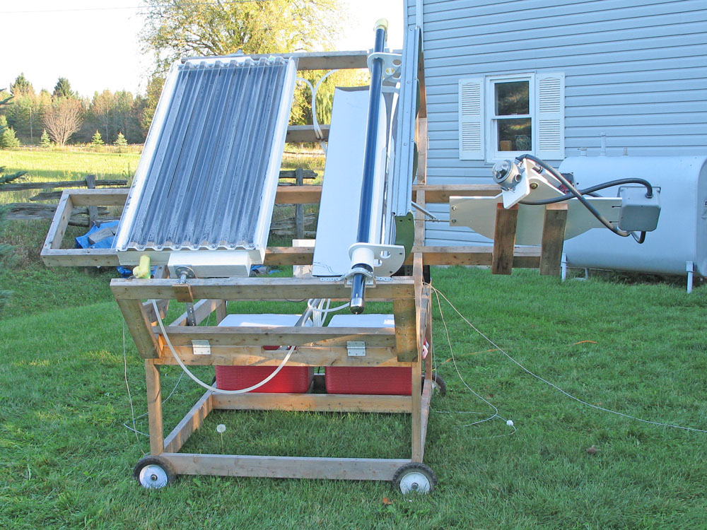
The evacuated tube was mounted in the solar test jig in the conventional manner of my concentrator design. Slightly enlarged holes in the hangers allows the reflector to simply hang from the evacuated tube (the reflector only weighs about 5 pounds) and to pivot around it. Small saddles were made with a semicircular opening just slightly larger than the evacuated tube OD for the tube to sit on and it is held in place with straps with padding strips on the underside and gentle pressure from the two mounting screws. The white cylinder is a 3" PVC pipe joiner which functions simply as a spacer, to keep the reflector from sliding down to the frame.

The evacuated tube collector is finished and ready for testing.

Index - Comparing concentrator to flat plate solar collector

Friday, October 07, 2011

Insulating the flat plate collector

The flat plate collector that I have been using in my comparative tests was constructed as a 1/2" baltic plywood box with 1" polystyrene insulation glued on the outside of the bottom. I did it this way so that I could use staples into the plywood to hold the aluminum absorber plates in place. The construction of my flat plate collector is described here.

Shown above in a bottom view (click to enlarge), you can see also the suspension beam and one of the pivots. The linkage arm sticking up out of the top of the picture normally faces downward and it allows the collector to be rotated to face the sun. One of the fluid inlet/outlet spigots can be seen on the end.

For glazing, I used SUNTUF corrugated polycarbonate glazing made by Palram Americas. Here is a view of the sealed flat plate collector with the Suntuf in place. Suntuf is crystal clear and very tough although the sheet polycarbonate it is made from is quite thin (0.75mm or 0.030") and it seems flippy until it is fastened in place.

You can see the "wings" on both sides. I found the Suntuff hard to cut and did not bother to make the two longitudiunal cuts that I would have had to make to have it fit the collector exactly. The "wings" serve no purpose but they do not affect the function either. It was just easier that way and I was worried about cracking the sheet while cutting.

I was a bit mystified by the plastic horizontal closure strips which I bought to use with the Suntuf. The wooden versions weren't available at the store. With those, I would have simply run a bead of one of the recommended sealants along the length of the top and bottom of the closure strip but these plastic ones are all perforated so that the sealant would just drop through the holes?

I added a subframe (the solid white strip below the brown closure strip) to the top of the flat plate collector and drove cushioned screws through oversize drilled holes in the Suntuf (as they recommend to allow for thermal expansion). The sealant I used was DAP 100% Silicone Rubber Sealant recommended by Suntuf. You can see how I carefully sealed the Suntuf to the top edge of the horizaontal closure strip. I am not sure how the manufacturer intends you to use this product, their literature is silent on the sealing method with the plastic closure strips. But this will do the job.

The insulated flat plate collector is now complete and awaiting further tests.

Index - Comparing concentrator to flat plate solar collector