 This is a great rainy day project: making ribs for your solar collectors. You'll need quite a few of them once you've decided to scale-up and make a larger working system. Each eight foot collector needs seven of these. Six collectors need 42 and so on. A general rule of thumb I heard for heating a swimming pool was to have one third to one half of the surface area of the pool in the collector, so you can start doing some math on your application.
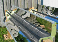
The ribs shown here are at various stages of completion. The green ones on the bottom have received the two-part marine primer sealer coat and are ready for the top coat. As these ribs are made from wood they need to be sealed from the weather.
All of the ones shown above are one half inch (also sold as 13mm) "baltic plywood" which is a terrific material to use where relative precision and strength are required in a panel material.
The white one with the extra large holes is experimental and has the final resin topcoat in white. The large holes give it more of a space age look but their actual function is to lighten the rib on the bottom of the collector panel to improve balance at the collector tube/pivot. I felt that I could remove material using the large sawtooth forstner bits that I bought to make the through holes for the collector tubes. The baltic ply material is very stiff and punching the holes does not seem to adversely affect the strength of the rib in the direction we need it to be strong (mostly lengthwise).
Making the large holes with a forster bit didn't work out very well with the plywood ribs, since without using clamps for each individual hole, the plywood tended to tear out at the back. Aside from the cosmetics, this created a problem for weathersealing and much patching and sanding was necessary to get a clear looking sample. This was solved but took more work. Each hole (there are nine in each rib) requires individually repositioning and clamping the rib to the drill press table, using two clamps, one on each side of the hole to keep the rib on the table firmly as the forstner bit comes through the rib.
I'm trying some ribs made from from MDF (medium density fibreboard) material which is also a fairly common furniture making material available at many home centers. We'll see shortly how the MDF comes out. You could also make the ribs from a plastic sheet material although I haven't tried that. I suspect that a plastic sheet of acrylic, lexan or UHMW would not have the stiffness of wood, although using plastic would eliminate the coating steps which are significant.
When selecting material for the ribs, the minimum thickness is the half-inch material used here but it could be thicker unless the weight became very much greater. Given that the design needs bolts sunk into the ends of the material with some precision lead me to the half inch material I am using.
 Here's my first batch of MDF ribs with the first jig on top of the stack. The funny handles are actually off-cuts from the band sawing rough cut operation but ended up being quite functional as hand grips to guide the jig and rib over the router table for the edge routing operation.
I can get ten ribs out of a 2x4 foot piece of material, since they are about 23 inches at the widest point.
The technique I use is suited to a small shop for hand production of a hundred or so ribs (a dozen collectors takes 84 ribs). I've thought that they also could be molded out of recycled plastic, but here I am individually making each one by cutting it out of a sheet and then routing the edge. The ribs above are sitting on my small routing table (the cheap kind with the hand router hanging upside down underneath).
 Here's another detail of the top of the jig on top of an MDF rib which has been edge routed using the jig. The 10cm refers to the focal length of the parabola made from this jig. This means that the copper tube is centered 10cm from the bottom of the reflector to achieve design focus.
The small metal strap is cut from a roll of galvanized strapping and used to brace the glued and screwed attachment of the off-cut handles to the jig (two more small screws come up thru the bootom).
The MDF rib has only a small burr which is removed by a light hand sanding. The edge is very nice with no breakouts. Of course, the inside edge is very much more important than the outside edge, since it is the inside that forms the basis for the curviture of the parabola. The metal rails hold the reflector sheet onto this edge. I estimate that with my jig and technique, I am achieving an accuracy on the parabolic curve of about a millimeter from the ideal.
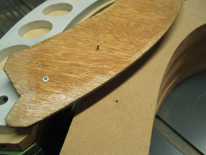 This is the bottom view of one end of the first jig. There are two of these short pins on the jig, one at each end. The pins are actually small steel nails of about 1mm diameter. They are epoxied into the jig and cut off so that about 3mm protrudes thru the bottom.
The two mating holes drilled into each ribs are actually the first step in making the rib, since they guide the loaction of all subsequent machining operations. The pins lock the jig to the rib.
The jig is handmade from 1/4 inch scrap and patched and filled, especially along the edge, to guide the ball bearing cutter mounted at the top of the router bit. The jig could have been made out of any type of material including metals like aluminum.
 There is a second jig for the ribs, and it is shown here on top of the stack, held in place to the top rib with two 1mm dia nails which fall into the locating holes marked with the first jig.
I'd originally thought to just have one jig, with the position of various holes marked in it, but the need for strong handles on the routing jig meant that some of the holes would be underneath the handles. So I simply used the first jig to make a copy out of another piece of 1/4 inch thick scrap and marked and drilled the location of the holes that would be necessary.
Using a small center punch, the second jig is used to transfer the location of all the holes to the top of each rib. Depending upon what type of rib it is (there are several variations), some holes are drilled, while others are omited, but all the holes are marked in this manner in each rib. These small dimples in the surface guide a drill bit's starting location in the subsequent operations.
 This is the top of the second jig, showing the highly accurate method of locating the jig using small nails. Remember that the accuracy I'm aiming for here is about a millimeter and this seems to be adequate for the purpose, using the simplest tools and equipment for the job.
The material here is 1/4 masonite which makes a good jig material. The jigs should last a long time, provided that you don't damage them. It's a good idea to make a spare or two, just in case.
Also you can see again the fine slivers of material on the top edge of the MDF. This is nothing to be concerned about. The edge is actually very smooth and precisely follows the jig. The fine sliver comes off easily with a light hand sanding.
It's not a solar day today since it's raining. Time for me to go and make some more ribs.